Last year the American Society of Echocardiography (ASE) released updated guidelines for cardiac chamber quantification by echocardiography. The ASE teamed up with the European Association of Cardiovascular Imaging to update the previous guidelines due to the rapid technological developments of the past decade and the changes in echocardiographic practice brought about by these developments.
The updated normal values, which include all four cardiac chambers, 3D echo and myocardial deformation, were determined on the availability of a considerably larger numbers of normal subjects, compiled from multiple databases. The last standards prior to this update were dated 2005. You can surely appreciate how the technological advancements in the past 10 years, regarding data collection and database sharing, would have provided a massive increase in accessibility to such a greater number of normal subjects. This increased data analysis of which explains why we saw changes in our normal reference ranges.
So here we are one year later, and as a consultant I spend a large part of my day reviewing echocardiograms and I can’t help but notice how many of the new recommendations are not being followed. I also see time and again examples of the sonographer truly trying their best to implement the new guidelines but unfortunately do not have the correct guidance or training to complete the measurements correctly.
I am writing this blog series to help simplify the new guidelines and to provide instruction for the correct technique for measuring cardiac chambers and vessels during a routine echocardiogram. This week I will cover the correct technique to accurately measure the left ventricle in 2D including:
When I first read the guidelines and learnt that the new recommendation was to use 2D to measure LV linear measurements I did my “yay- no more M-Mode jig”. Over the years I have seen some crazy off axis M-Mode measurements so I couldn’t have agreed more with ASE regarding using 2D measurements to avoid oblique measurements and to facilitate accurate perpendicular measurements. The recommendation was to perform this in the parasternal long axis view. Sadly the ‘no more M-Mode’ grin didn’t last long!
As facilities made an effort to comply with the new standards I started to see more 2D measurements of the LV in the parasternal view but the location of the calipers and the timing of the end diastole/systole measurements had errors. As sonographers, we have become accustomed to training our eyes on the correct point of the M-Mode cycle to measure the LV and now we are required to decide exactly where to measure the LV and to select the exact frame of the cardiac cycle.
I realized that all the past training was focused on correct M-Mode techniques and all of a sudden M-Mode was replaced with the requirement for 2D measurements with often very little or no extra training provided for sonographers.
I will review the fundamentals of the correct techniques for accurate LV measurement, explain the timing of end diastole/systole in regards to linear measurements, discuss caliper location and outline 6 pitfalls to avoid when measuring the left ventricular wall and chambers.
Some fundamental techniques to measuring the left ventricle in systole and diastole are:
The LV is measured at end diastole and end systole. That’s what the ECG is for, right? Wrong! When measuring the left ventricle we are focusing on the mechanical activity and not the electrical activity. The electrical and mechanical activity does not always occur simultaneously. In 2D imaging the end diastolic frame often occurs after the QRS complex and the end systolic frame occurs after the T wave on the ECG tracing. What’s an easy way to determine end diastole/systole? Look at the MV and AV to guide you.
End-diastole: LV is at its largest dimension – frame immediately after the MV closure
End Systole: LV is at its smallest dimension – frame immediately after the AV closure
So the main goal is to always be perpendicular to the structure you are measuring. I think one of my most recent aha moments regarding this was during the review of an ASE educational learning module that explained that with 2D measurements you have the flexibility to truly be structure specific regarding perpendicular measurements. No more measuring straight down the line, like in M-Mode. Now, as sonographers, we have the ability to measure each structure on its own perpendicular axis as sometimes the walls and the chamber do not follow the same axis. This flexibility of no longer measuring in a straight line also made it permissible to measure the LV wall and chamber at slightly different locations to ensure accurate measurements, as long as they are all in the basal segment of the heart.
We have reviewed the fundamentals of the correct techniques for accurate LV measurement and you now have a better understanding of the timing of end diastole/systole in regards to linear measurements and caliper location. Let’s now review 6 pitfalls to avoid when measuring the left ventricular wall and chambers.
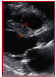
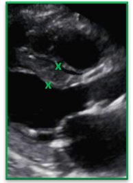
Be careful when measuring the IVS in the presence of right ventricular trabeculations
| Incorrect | Correct |
| The trabeculation was measured as part of the IVS measurement causing the thickness of the septum to be over estimated | The gains, TGCs and focus were adjusted to help clearly define the endocardial border and the RV trabeculation. The IVS was correctly measured and did NOT include the trabeculations |
 |
 |
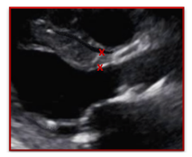
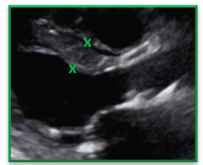
Avoid measuring a thickened septum as it narrows closer to the aortic root. Measure the IVS slightly more apically than usual to measure the true thickness of the septum
| Incorrect | Correct |
| The septum was measured at the tapered section of the IVS which under estimates the true thickness and severity of left ventricular hypertrophy | The calipers were placed more apically allowing for the full thickness of the septum to be correctly measured. As long as the measurement remains within the basal section of the heart it is ok to choose a location that allows for a more accurate measurement |
 |
 |
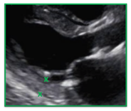
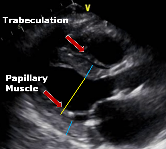
Be careful how you measure the posterior wall and the LV in the presence of prominent papillary muscles. The papillary muscle falls within the LV dimension and not the posterior wall dimensions.
| Incorrect | Correct |
| The papillary muscle was measured as part of the posterior wall which overestimates the size of the posterior wall. | Careful attention was paid to the endocardial border of the posterior wall and the anechoic space separating the papillary muscles from the wall. |
 |
 |
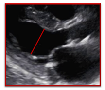
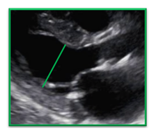
| Incorrect | Correct |
| The left ventricle was not measured to include the entire LV cavity and stopped short at the papillary muscle which underestimates the LV size | The left ventricle was correctly measured all the way to the PW interface. By recognizing that the papillary muscle is included within the LV cavity measurement the LV is not underestimated |
 |
 |
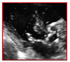
Measurements are perpendicular to the structure being measured – remember to be structure specific when assessing the plane. The IVS, LV, PW measurements do not have to be in a straight line. As long as all the measurements are within the basal section of the heart focus on the best caliper placement based on the structure you are measuring.
| Incorrect | Correct |
| The heart is off axis in this image and the sonographer used the imaginary plane of the M-mode cursor to determine caliper placement instead of paying attention to the plane of the LV. | In this image we see the LV measurement corrected to reflect the perpendicular measurement of the LV |
 |
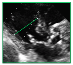 |
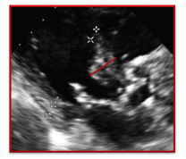
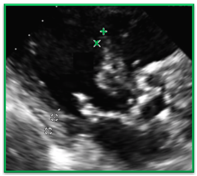
In the presence of sigmoid septum – do not measure the bulge of the septum be sure to measure the septum just apical to the bulge. The same carries through for the LV; measure the LV cavity apically to the bulge of the Sigmoid Septum.
| Incorrect | Correct |
| It would be incorrect to measure the IVS in the bulge of a Sigmoid Septum. The sonographer was correct to measure more apically | In this image the sonographer correctly measured the IVS more apically than usual to avoid the bulge. |
 |
 |
Remember you have lots more flexiblity now that you are no longer stuck to the constraints of your M-Mode cursor. You get to decide where you place your cursor when measuring each structure. You no longer have to measure in a straight line. Pay attention to the structure you are measuring in regards to the best location and the correct perpendicular plane. Remember the left ventricular walls and chamber will not always lie on the same plane so don’t be afraid to change the plane when measuring walls and chambers in one view. Below is an image that summarizes many of the pitfalls we discussed.
In the first blog of our new Chamber Quantification Correct Techniques series we discussed why the new quantification guidelines were released and reviewed the fundamentals for accurate LV measurements in the parasternal long axis view. I hope you now have a better understanding of the correct frame and location of your LV linear measurements. Maybe my ‘aha moment’ will be your epiphany too and you will be free to focus on each individual structure of the heart as we break away from the concept of measuring straight down the line.
In the future, as we review the new guidelines, we will discuss correct techniques for assessing:
Sign up for our newsletter and follow us on facebook to get the most up to date news on cardiovascular imaging!
Lang et al. (2016). Http://ljournal.ru/wp-content/uploads/2016/08/d-2016-154.pdf. Journal of the American Society of Echocardiography,28(1), 1-39. doi:10.18411/d-2016-154
https://pdfs.semanticscholar.org/f90b/b525a3a8707778e9841288ab47f7c421d510.pdf


Jun
2016
Jun
2017
Aug
2016
Sep
2016
Sep
2016
Sep
2016
Sep
2016
Sep
2016
Sep
2016
Nov
2016
Nov
2016
Mar
2017
May
2017
May
2017
Aug
2017
Aug
2017
Oct
2017
Oct
2017
Jun
2019
Aug
2018
Jan
2021